To get to know my 3D printer I decided to embark on a redesign of Felix, a small quadruped robot.
I settle on the following set of constrains for this project:
It should be a bolt/screw free assembly
The actuators should be housed on the body, not on the legs
It should be possible to print it on an entry level printer with a relative small printing area – like mine =)
My first iteration was based on a previous parallelogram design.
But I wanted the robot to be able to crouch and lay down, and this kind of lever system restrict the range of possible movements. Besides early versions have pinched my fingers more than once, so I wanted to try some sort of enclosed mechanical transmission.
I start experimenting with other means of transmission. First, an elastic tension belt. But the belt slipped under weight. Increasing the tension on the belt provided more traction but gave the servos a hard time controlling the leg.
Next, I try a timing belt printed with Ninja Semiflex. It kind of worked but not reliably enough. Though playing with Semiflex was a great learning experience. Changing the timing belt with a peg/hole belt system didn’t help much either.
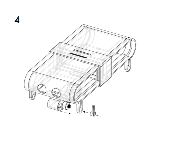
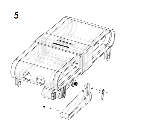
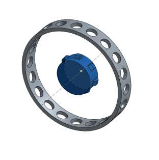
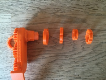
To hold the leg on to the chassis I manage to print a usable threaded collar.
To make the collar I followed one of the tutorials from the OnShape learning guide: https://www.onshape.com/cad-blog/tech-tip-creating-a-thread.
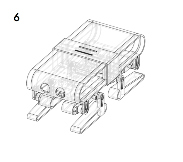
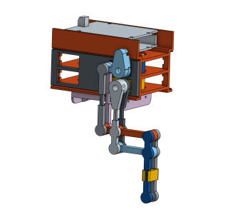
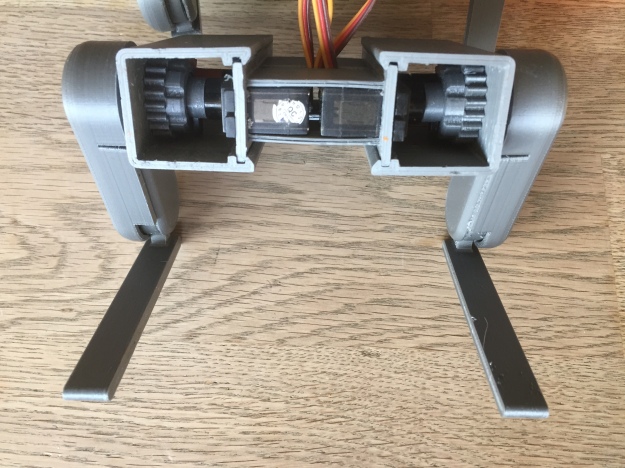
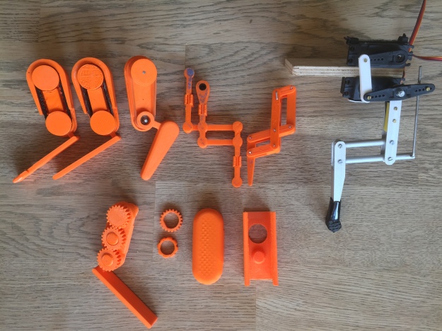
Complete hind legs assembly with servo casing
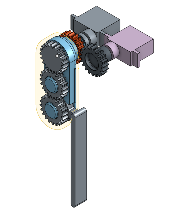
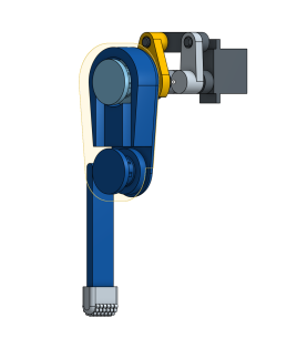
When the femur servo moves the shin angle changes accordingly. The software controlling the leg has to take that into account and manage the position of the shin by adding a delta calculated from the existing femur angle.
Having the possibility to print and test parts allows me to try subsets of a given design or a mechanical concept. I can go through several iterations at a quick pace and learn about tolerances of the material, and how part orientation affects structural integrity and print quality.
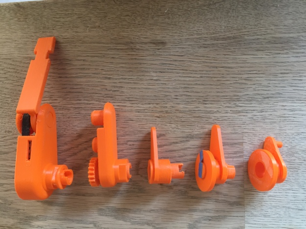
Multiple design iterations side by side
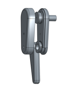
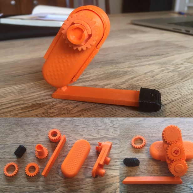
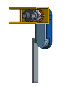
Prototyping the transmission for the shin through the femur