To get to know my 3D printer I decided to embark on a redesign of Felix, a small quadruped robot.
I settle on the following set of constrains for this project:
It should be a bolt/screw free assembly
The actuators should be housed on the body, not on the legs
It should be possible to print it on an entry level printer with a relative small printing area – like mine =)
My first iteration was based on a previous parallelogram design.
But I wanted the robot to be able to crouch and lay down, and this kind of lever system restrict the range of possible movements. Besides early versions have pinched my fingers more than once, so I wanted to try some sort of enclosed mechanical transmission.
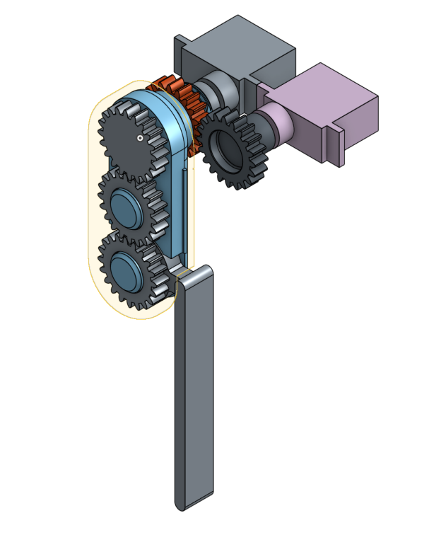
I start experimenting with other means of transmission. First, an elastic tension belt. But the belt slipped under weight. Increasing the tension on the belt provided more traction but gave the servos a hard time controlling the leg.
Next, I try a timing belt printed with Ninja Semiflex. It kind of worked but not reliably enough. Though playing with Semiflex was a great learning experience. Changing the timing belt with a peg/hole belt system didn’t help much either.
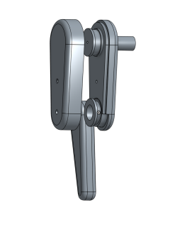
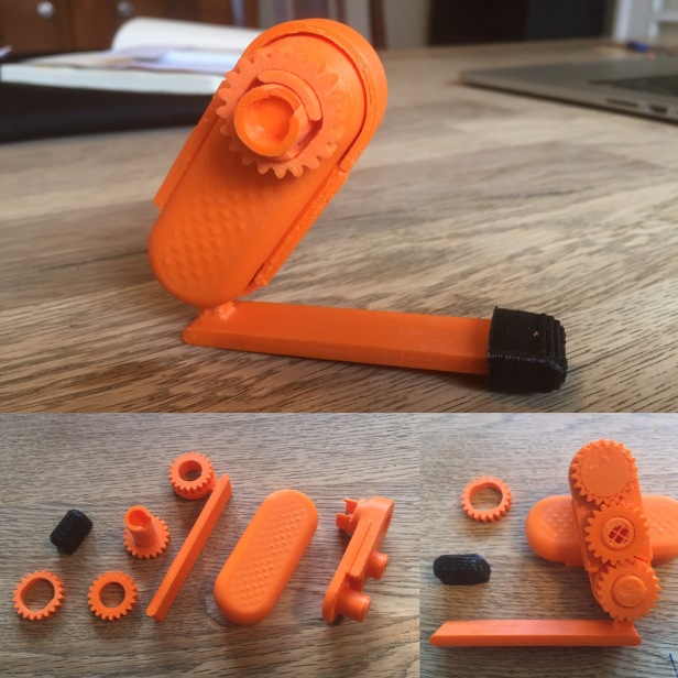
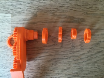
To hold the leg on to the chassis I manage to print a usable threaded collar.
To make the collar I followed one of the tutorials from the OnShape learning guide: https://www.onshape.com/cad-blog/tech-tip-creating-a-thread.
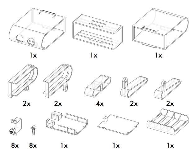
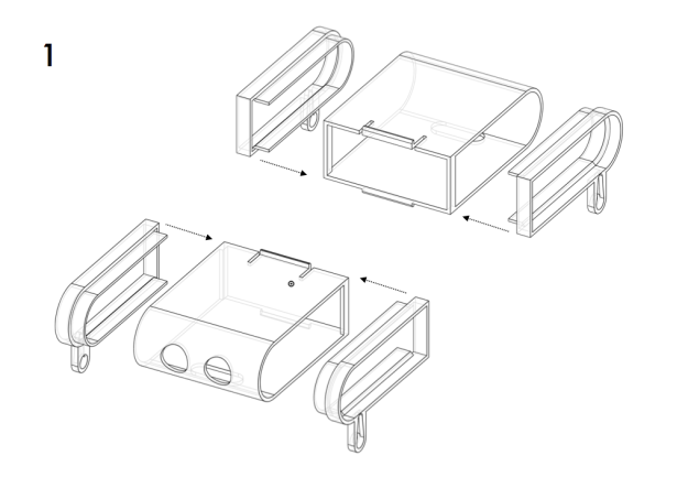
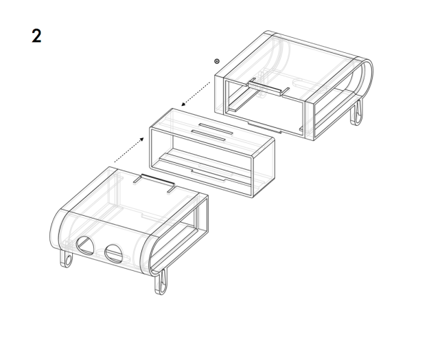
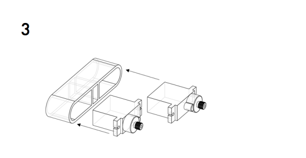
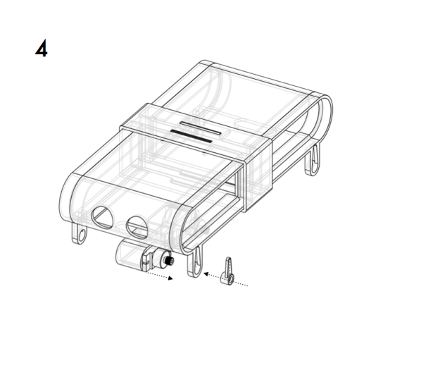
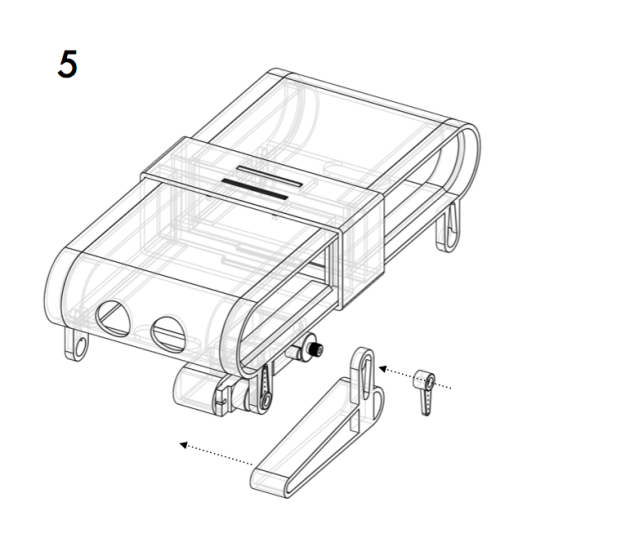
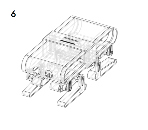
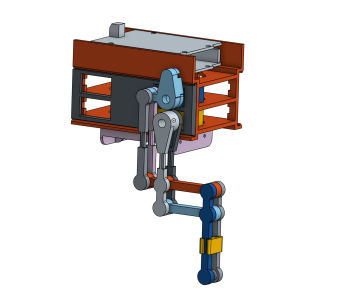
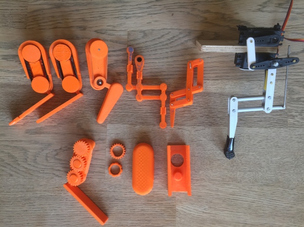
Complete hind legs assembly with servo casing
When the femur servo moves the shin angle changes accordingly. The software controlling the leg has to take that into account and manage the position of the shin by adding a delta calculated from the existing femur angle.
Having the possibility to print and test parts allows me to try subsets of a given design or a mechanical concept. I can go through several iterations at a quick pace and learn about tolerances of the material, and how part orientation affects structural integrity and print quality.
Multiple design iterations side by side
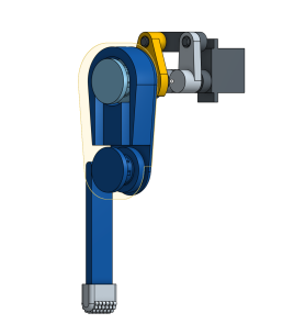
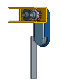
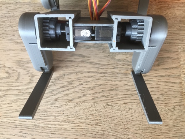
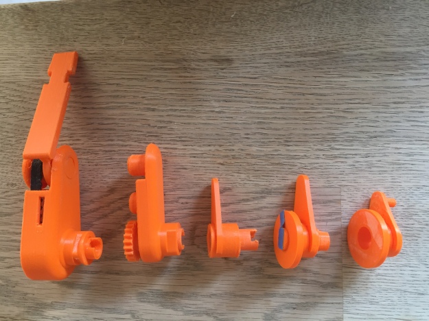
Prototyping the transmission for the shin through the femur
But I want a simple tool to create and manage gaits and animations for legged NodeBot critters.
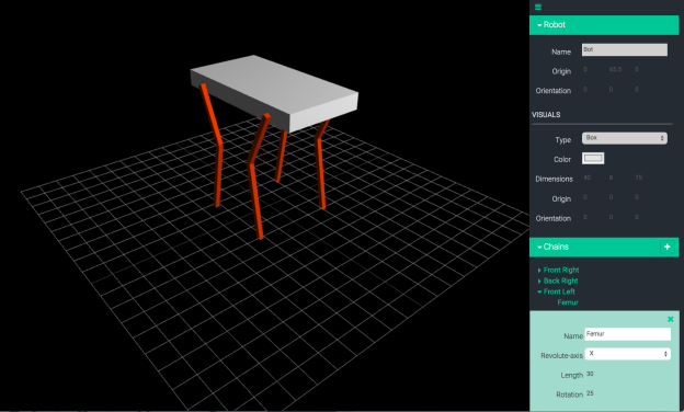
So I start working on a small browser-based simulation system, mostly as an excuse to explore some web technologies currently missing in my toolbox.
The system will consist of an editor to define the geometry of the NodeBot, and a timeline to control its motion.
The most common method for describing the geometry of a robot, is URDF (http://wiki.ros.org/urdf). URDF stands for Unified Robot Description Format and it is the standard ROS (http://www.ros.org) XML representation of a robot model.
Almost any robot can be described as a kinematic chain of links attach to each other by joints. The least amount of information we need in our system is the length of the links and the type and orientation of the joints. URDF is overkill for this project, so the internal format will be a simple JSON structure.
The editor will be able to save, edit and load geometries. It will also provide tools to customize the visual representation of links and upload STL files to replace the default boxes and cylinders.
The timeline will allow motion control at a higher level than single joint positioning.
It should be able to control the position of a chain’s end-effector using inverse kinematics, to calculate the rotation of the individual joints. The calculation will be perform by Tharp (https://github.com/dtex/tharp), an Inverse Kinematics solver, develop by Donovan Buck (@dtex).
I will like to add a screen to Felix to eventually give some status feedback, but mostly to display/animate eyes. Sort of the way Baxter from Rethink Robotics does it.
To mount the screen I designed two head pieces and cut them with on the laser-cutter.
The head is controlled by two HXT900 servos. One servo rotate the head from left to right and the other to tilts the head. The rotation is to allow the two SHARP 2Y0A21 proximity sensors to scan the room. The tilt is just cute.
Besides the screen and sensors I also added a small piezo speaker.
I’m happy with the result, now time to do the wiring.
Mini Felix is a noisy and jittery fellow. Walking is ok, but doing animations with it is quite annoying. Instead I decided to assemble a new chassis using the latest design and use it to test the animation tool. At the same time I wanted to document the assembly so I can write a step-by-step tutorial. Putting it all together took about 4 hours and there are a couple of things I can do to improve the design to ease this process. Today I did the soldering and connected the servos and was able to start playing with the animation editor. More on that later.
Lately there has been a renewed interest in the field of soft robotics. Big Hero has probably something to do with it =).
Anyway, Harvard Biodesign Lab released last year a soft robotics toolkit. Doing some sort of project with the kit has been on my radar since, but I haven’t had an specific idea. But today a small centipede decided to walk by and I took a short clip in order to get a better idea of how he moved. Trying to mimic the locomotion pattern could be an interesting project.
This week I got a bunch of 9G servos and some PMW motor shields from my local Adafruit pusher m.nu. I want to use them in a smaller (more affordable) version of Felix.
The redesigned chassis is just a scaled down version of the current geometry, but I have to work on the casing for the electronics. There is not much space available for a Uno, a shield and a battery pack. If I lay the electronics down flat, Felix looses it’s slender figure and looks more like a turtle. Currently I’m working on a vertical arrangement, which gives him a unflattering hump, but he seems to prefer that.
Before I settle/refine the design, I have to test how it affects Felix balance during the gait.
I’ve been working today on the design for Felix, trying to tidy up the space for the electronics. The new body template is designed to fit an Arduino Uno board and an Adafruit 16×12 servo shield.
I’m trying to get up to speed with Autodesk Fusion 360. It’s great software, but to do this sort of stuff I keep coming back to OpenSCAD.
In order to get some “Fusion time”, I exported the template from OpenSCAD to STL format and uploaded it to Fusion 360. I also downloaded 3D models of an Arduino and a HiTech Servo from GrabCAD.com. Then I spend some time playing with the render:
I still need to add a license file to the repo, but it’s a regular MIT license.
And speaking of CAD, I recently wrote a post for Makezine: http://makezine.com/2015/04/20/understand-1700-mechanical-linkages-helpful-animations/. It’s a short highlight of Mr. Đức thắng Nguyễn’s YouTube Channel. The channel is an amazing collection of complex animated mechanism he has documented with Autodesk Inventor over the last 10 years.
Felix is a NodeBot (http://nodebots.io). A NodeBot is a JavaScript powered robot. One of the benefits of using JavaScript and Node, is that it makes it trivial to create a web based dashboard for your project. My dashboard has a simple joystick that controls Felix using Socket.io.
You can see a clip of Felix and the dashboard here:
Yesterday I spend sometime at my local #fablab #fablabnordvest learning to know their Chinese Laser cutter. I used 4mm. white acrylic.
The design was made with #iDraw and exported to SVG (You can download the SVG here Body.svg). But my Chinese friend only speaks DXF or AI. After importing the converted AI file, I realised that I needed to do some cleanup of the path. Some of the patterns appeared twice(?).
Anyhow, it’s always mesmerising to watch a machine do it’s work.
After playing with the assembly, I want to redesign the way the lid is attached and I will like to make a smaller version for 9g servos. Probably the easiest way to do this is to use OpenSCAD to create a parametric model with the size of the servos as a dynamic variable, and then create a projection which I can export to DXF.