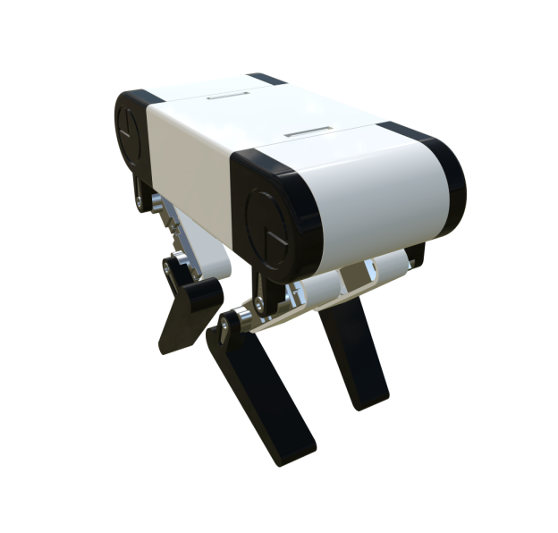
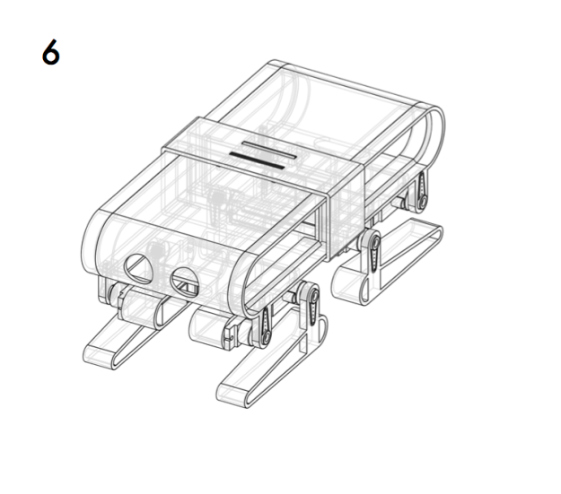
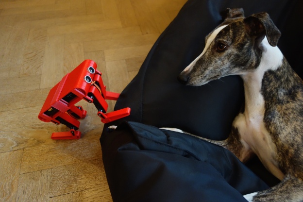
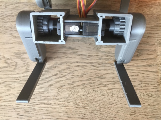
One of the first thing I have printed is a new design for my 8DOF small quadruped robot. I like the embossed details on the hip pieces and the battery holder mech.
You can download the files from Pinshape or Thingiverse:
Let’s review how to we get Felix a 3D printed quadruped robot to walk. Start by downloading or cloning the code from GitHub (https://github.com/Traverso/Felix3D).
If you haven’t done it yet, get Node.js and install/setup Johnny-Five to communicate with your microcontroller/board.
Getting Felix to walk properly requires some tweaking. We will try to compensate in software for a number of small imperfections in hardware that eventually add up.
You have (or should had) already done a rough calibration of the servos and leg assembly. Now let’s test one leg at a time.
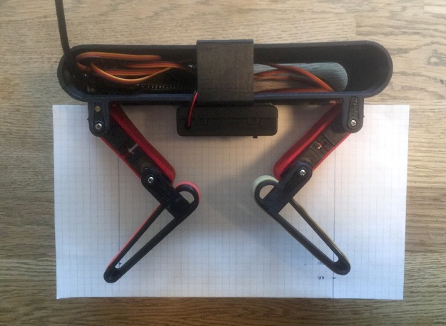
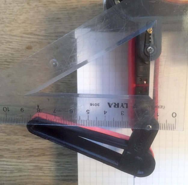
To increase precision get a sheet of graph paper, glue it to some cardboard to add stiffness. Place it between Felix legs like this:
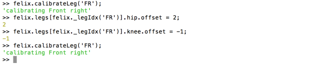
Now copy/write your calibration offset to the index.js file
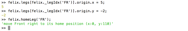
Run the index.js file. A reference to felix is injected to the REPL.
From the REPL you can call:
Update the values directly in the REPL and recalibrate until you get it right:
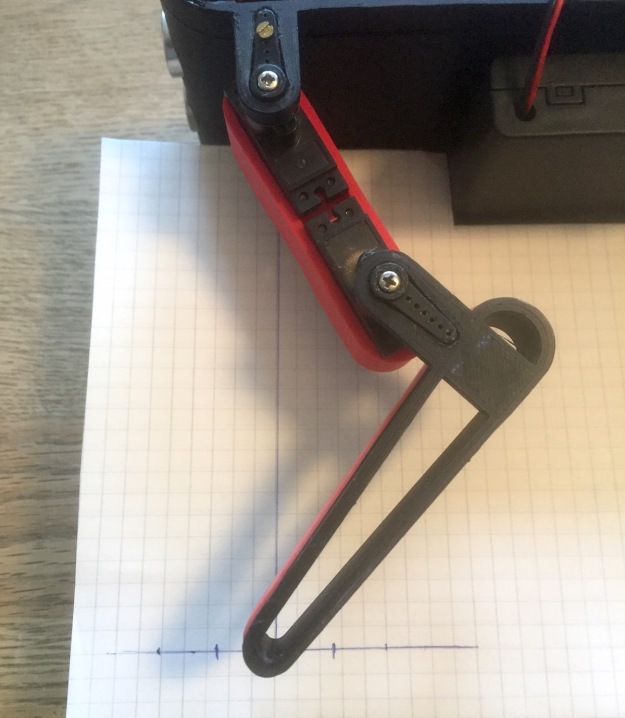
Now, control the home position of the leg:
Use the graph to check that the tip of the leg hit it’s mark: directly 110 millimeter beneath the hip joint.
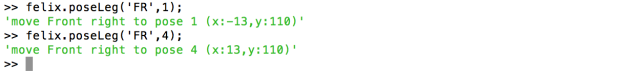
Next, control the two furthest points of the step:
If the home position and the step-pose position are off, you can tweak the leg’s origin values:
Once you are satisfied with your angles offsets and your origin offset, remember to update the values in the index file. Repeat this steps for the next tree legs.
Now let’s try some walking. Press the “arrow up” key and Felix will start a creeping gait by running the forward method. Press the space bar to pause and resume the walk.
This method generates a walk cycle based on the current step properties, set the state and start running the scheduler.
The scheduler consumes an array of “frames”. The rate at which the frames are processed is controlled by the “speed” configuration value.
A frame consist of a command and a payload. Currently they are two types of frames, a control frame like:
{cmd:'loop',count:-1}
When the scheduler encounter this frame it loops back to the start of the scheduler and decrements the count value. If the count value reach zero the schedule continues with the next frame. For an infinite loop the count value can be set to -1.
When the scheduler encounter this frame, it will position each leg joint to the provided angles.
The generated walk cycle is a creeping gait (or static stable gait) where the body is moved forward at the same time that the stepping leg is being lifted.
An alternative (more stable, but slower cycle) can be implemented by shifting the center of mass first and then lifting the stepping leg.
To generate the cycle, a step is divided into four key-poses. From pose one to four the legs push the ground behind shifting the body along. In pose four the leg is lifted in a semicircle back to pose one.
A gait is described as an array of poses:
//expected leg order FR, FL, BR, BL
gait: [
   [1,2,3,4],
   [2,3,4,1],
   [3,4,1,2],
   [4,1,2,3]
]
Felix currently master two creep gaits, the “cat” and the “deer”. In the cat gait the sequence of lifted legs is:
front-right
back-left
front-left
back-right
In the deer gait the sequence is:
front-right
back-right
front-left
back-left
From one pose to the next the needed transition points are generated by two methods: “_linearTrajectory” and “_ellipticalTrajectory”.
Felix.prototype._linearTrajectory = function(line,
                                             granularity,
                                             skip_start_point){
    var trajectory = [];
    var granularity = granularity || 8;

    //find the slope/delta
    var delta_x = line.b.x - line.a.x;
    var delta_y = line.b.y - line.a.y;

    //calculate the distance between the two points
    var distance = Math.sqrt( ((delta_x) * (delta_x)) +
                              ((delta_y) * (delta_y)) );

    if(distance == 0) return [];

    //divide the line int the required number of points
    //decrease the granularity one step to be able to include
    //the end point
    var skip = (skip_start_point)? 0:1;

    var step_size = distance / (granularity - skip);
    var c_step = (skip_start_point)? step_size:0;

    for(var i=0;i < granularity;i++){
        var inc = c_step / distance;

        trajectory.push({
                          x:Math.round(line.a.x +
                           (inc * delta_x)),
                          y:Math.round(line.a.y +
                            (inc * delta_y))
                        });
        c_step+= step_size;
     }
     return trajectory;
}

Felix.prototype._ellipticalTrajectory = function(arc,
                                                 granularity,
                                                 skip_start){
      var trajectory = [];
      granularity = granularity || 8;

      //divide the angles int the required number of points
      //decrease the granularity one step to be able to include
      //the end point
      var skip = (skip_start)? 0:1;
      var step_size = (arc.end_angle - arc.start_angle) /
                      (granularity - skip);
      var c_angle = arc.start_angle;

      if(skip_start_point) c_angle+= step_size;

      for(var i=0;i < granularity;i++){
        var x = arc.origin.x + arc.radius.x *
                Math.cos(Math.radians(c_angle));

        var y = arc.origin.y + arc.radius.y *
                Math.sin(Math.radians(c_angle));

        trajectory.push({ x:Math.round(x),y:Math.round(y) });
        c_angle+= step_size;
      }
      return trajectory;
}
The number of transition points in both methods are governed by the configuration variable “granularity”.
The points generated for the poses and transitions are then converted to angles using the Inverse kinematics method described in a previous post. This angles are added to the frame, and the frame is added to the scheduler.
For the next step is best not to have the thighs/femurs attached (to avoid the risk of striping the servos gears).
Edit the pin number in the script (legs.hip.pin, etc) to match your setup’s connections and run the script. This will set all servos to 90 degrees.
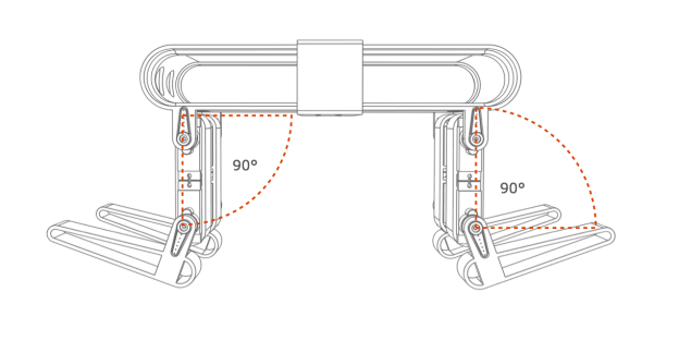
Now attach the thighs/femurs. The femurs should form a 90 degrees angle in relation to the body.
The shins should also form a 90 degrees angle, but be aware that the shin is slightly lifted as the angle should be from the tip of the shin to the femur (as seen in the graphic).
Due to the coarseness of the teeth on the servo horns the resulting angles might be off by a couple of degrees. To get it as close as possible edit the offset values in the script (legs.hip.offset, etc). For example if the front right femur is off by 2 degrees to the left set the offset value to legs.hip.offset = -2.
Run the script again and check (preferably with an angle ruler) that all segments are correctly positioned.
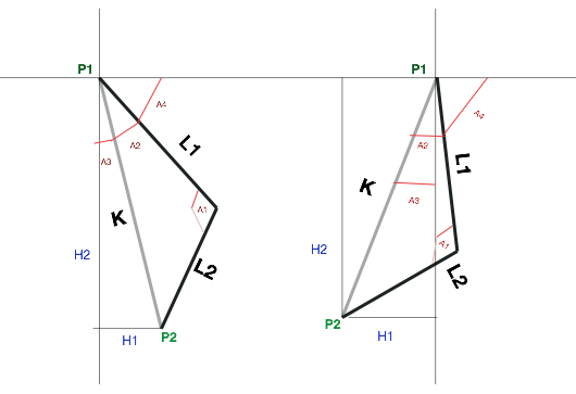
This is a short explanation of how to calculate the leg angles in our quadruped robot using basic trigonometry. If you don’t need the explanation but just want an example implementation scroll to the bottom to see the code sample.
As you can see in the graphic above, we want to find the angles A1 and A4:
A1 is the rotation angle of our first segment around the hip joint
A4 is the rotation angle of our second segment around the knee joint
What we know is L1, L2, P1 and P2 where:
L1 is the length of our femur
L2 is the length of our tibia
P1 is the origin point, or position of our hip (0,0)
P2 is the requested end position (or destination) for the feet
So, basically we want to how (much) does our hip and knee need to rotate in order for our feet to reach the requested end position.
We can calculate our knee angle using the law of cosines (https://en.wikipedia.org/wiki/Law_of_cosines). But to do so we need to know the length of the tree sides of the triangle L1, L2 & K.
So we start calculating our missing side K. We find the to segments H1 and H2 using the delta between our origin (P1) and our destination (P2):
int H1 = P2.x - P1.x; //delta on the x axis

int H2 = P2.y - P1.y; //delta on the y axis
//angle between L1 & L2 - the to segments, femur and tibia

float A1 = acos(( pow(L1,2) + pow(L2,2) - pow(K,2))/ (2 * L1 * L2));
Getting our hip angle is bit more convoluted. We need to find the angle A2 (no problem, having the tree sides is just more law of cosines), and A3 (another right-angled triangle – more Pythagoras).
//get the angle between the hypothenuse and the first segment (femur)

float A2 = acos( (pow(K,2) + pow(L1,2) - pow(L2,2)) / (2 * K * L1));
//get the angle between the hypothenuse and the x axis
float A3 = asin(H1/K);
Then we add this to angles and subtract the sum from 180 degrees and we are left with our hip angle.
float A4 = (PI / 2) - (A2 + A3);
Below you can see a function implemented for an Arduino sketch.
/**********************************************************

* Inverse Kinematic function for a two link planar system.

* Given the size of the two links an a desired position,

* it returns a pose struct with angles for both links

**********************************************************/

struct pose IK(int L1, int L2, struct point P2)

{

struct pose a;

struct point P1 = { HIP_ORIGIN_X, HIP_ORIGIN_Y }; //origin point (hip)
int H1 = P2.x – P1.x; //delta on the x axis
int H2 = P2.y – P1.y; //delta on the y axis
//this is the hypothenuse between the origin and the target
float K = sqrt( pow(H1,2) + pow(H2,2));
//the hypothenuse can not be larget the the sum of the segments
if( K > (L1 + L2 )) K = L1 + L2;
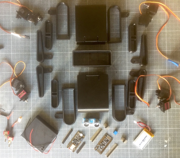
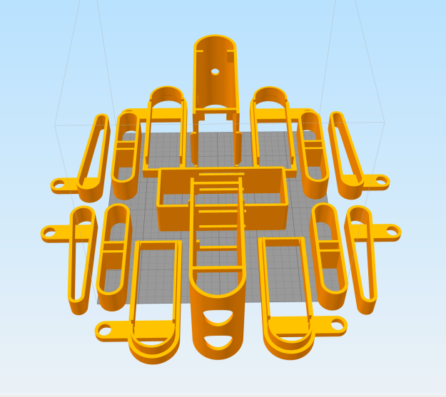
A contest on Pinshape (https://pinshape.com/contests/design-for-electronics-contest) got me to simplify the design of Felix and optimise it for 3D printing. The focus was on minimal support material, fast print time and optimal orientation on the print bed for best first layer adhesion. Other concerns where easy of assembly and sturdinnes of the final robot.
If you want to edit/customise the 3D model, you are free to copy my OnShape project using this link: https://cad.onshape.com/docume…
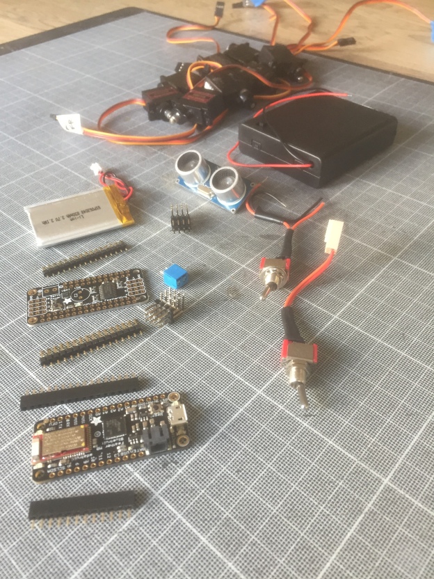
There ain’t much room for my current electronics setup. The servo connectors require a lot of space – even using angled pins. So I have ordered a feather board and a servo feather wing from Adafruit. The feather board has the added bonus that it can be controlled via Iphone/Android using Bluetooth.
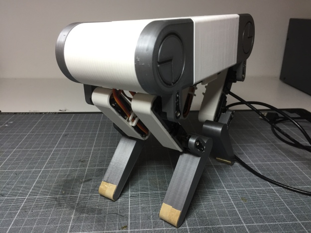
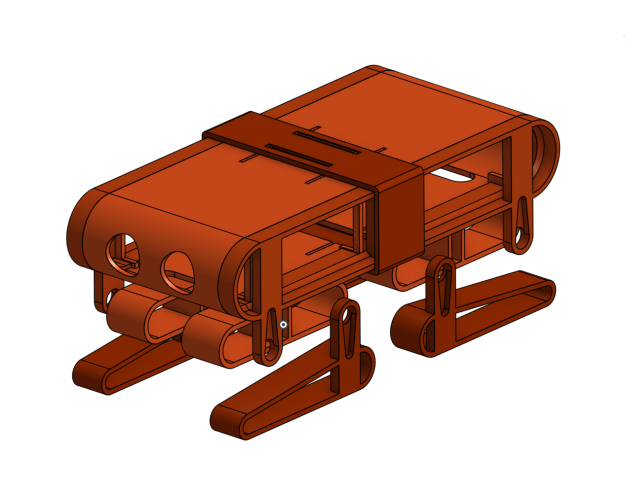
To get to know my 3D printer I decided to embark on a redesign of Felix, a small quadruped robot.
I settle on the following set of constrains for this project:
It should be a bolt/screw free assembly
The actuators should be housed on the body, not on the legs
It should be possible to print it on an entry level printer with a relative small printing area – like mine =)
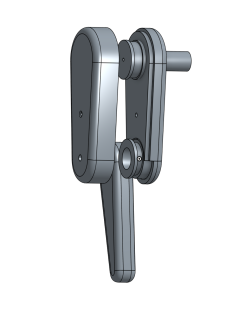
My first iteration was based on a previous parallelogram design.
But I wanted the robot to be able to crouch and lay down, and this kind of lever system restrict the range of possible movements. Besides early versions have pinched my fingers more than once, so I wanted to try some sort of enclosed mechanical transmission.
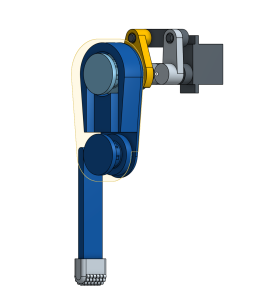
I start experimenting with other means of transmission. First, an elastic tension belt. But the belt slipped under weight. Increasing the tension on the belt provided more traction but gave the servos a hard time controlling the leg.
Next, I try a timing belt printed with Ninja Semiflex. It kind of worked but not reliably enough. Though playing with Semiflex was a great learning experience. Changing the timing belt with a peg/hole belt system didn’t help much either.
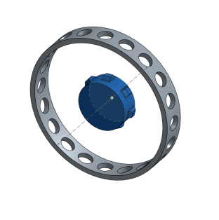
To hold the leg on to the chassis I manage to print a usable threaded collar.
To make the collar I followed one of the tutorials from the OnShape learning guide: https://www.onshape.com/cad-blog/tech-tip-creating-a-thread.
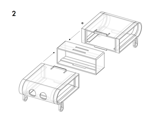
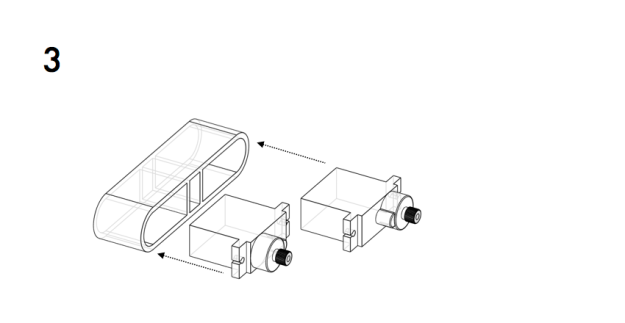
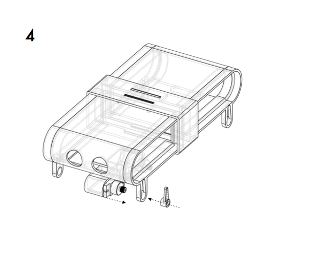
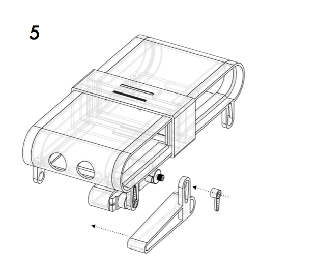
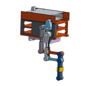
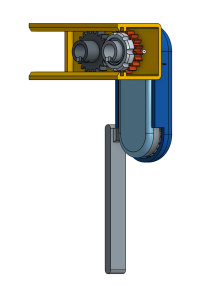
Complete hind legs assembly with servo casing
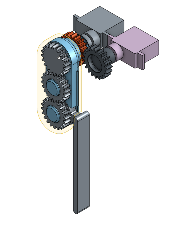
When the femur servo moves the shin angle changes accordingly. The software controlling the leg has to take that into account and manage the position of the shin by adding a delta calculated from the existing femur angle.
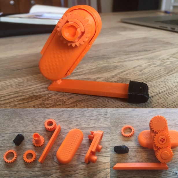
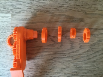
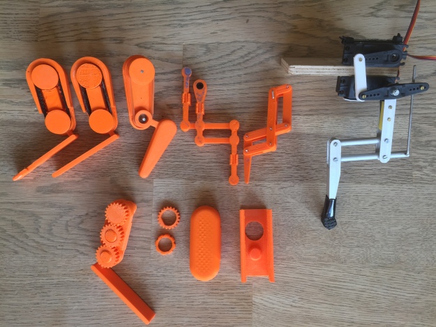
Having the possibility to print and test parts allows me to try subsets of a given design or a mechanical concept. I can go through several iterations at a quick pace and learn about tolerances of the material, and how part orientation affects structural integrity and print quality.
Multiple design iterations side by side
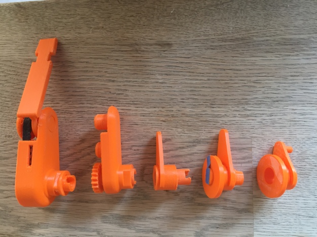
Prototyping the transmission for the shin through the femur
Last year I finally bought a 3D printer. In retrospect I should have done this a long time ago.
I used to believe that you needed a high-end machine to create usable parts,
and that anything less was a waste of time. There where toys only capable of churning out useless trinkets.
Boy I was wrong. Anybody interested in mechanical engineering or industrial design should get one immediately.
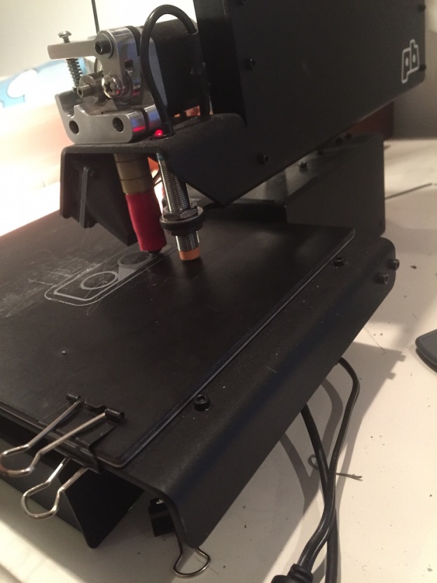
I got a Printrbot metal simple kit. My appreciation for 3D technology is colored by my personal experience with this particular machine, that turned out be an amazing piece of equipment.
Sturdy, reliable, elegant and honest in its design, the simple metal has performed well beyond my expectations.
One of the reasons I was holding back my purchase, was that I was afraid that after a couple of week of tinkering, the machine will be collecting dust on a corner. But to the chagrin of the rest of my family, the Printrbot is constantly churning out parts.
Currently, I’m even considering getting a Ultimaker or a Lulzbot Taz, not to replace my Printrbot but to extend my build size and printing capacity.
Setup
At the same time last year I start evaluating OnShape a cloud based professional CAD solution. I have used Autodesk Fusion 360 on and off for some time, but the chemistry wasn’t there. I do think Fusion is an amazing piece of software and I still use their CAM and rendering features, but modeling on OnShape just “clicked” with me from day one.
My current workflow looks like this:
I’ll do my modeling on OnShape, export the part to STL, slice the part in Simplify3D and sent the G-code to Octoprint.
On a side note, before upgrading your hardware get Simplify3D!
Design
Having a 3D printer at hand allows you to develop your designs skills at a fast pace.
You can iterate over small aspects of your design until you get them right.
Say, two parts need a snap-click assembly. You can isolate the snap-click features and print only the relevant sections, until you get the tolerances and amount of material right. Then you add those sections to your main parts.
You will learn a lot about designing within the constrains of a production method.
In 3D printing, orientation plays a crucial role.
Orientation impacts the level of precision you can achieve on a given surface.
Because parts consists of layers, the forces they can withstand vary depending on the direction applied.
In order to get the ideal orientation for a critical aspect of your design, you will sometimes need to split a part into discrete components.
The filament (type of material) and the chosen extrusion settings can have an impact in tolerances.
For mechanical parts where you need a higher level of precision, you are better of with slower speeds and low heat.
When you get orientation right, the (usually unwelcome) striation,
suddenly became an esthetic asset that reinforce the structural ideas behind your design.
Holding such a piece in your hand with the original digital model still on-screen is remarkably satisfying.
It’s and idea materializing out of thin air, and it feels like magic.
If you already have or want to buy a 3D printer, don’t forget that it’s not about the technology, but about what you can imagine.
Resources
Hardware
I own a Simple metal, but have I played with, and can recommend the Ultimaker and the Taz.
Filament
Don’t be cheap on the filament. You are not going to use that much, and quality shows. Recommended brands are Colorfabb & Monsterfil.
First layer adhesion
I start using blue tape (3M ScotchBlue 2090 Painter’s tape from Amazon or from Adafruit ) with mixed results. Printing larger flat surfaces without warping was a challenge, until I start heating the printer bed with a heat gun.
Because the bed on the Printrbot is solid metal, it could accumulate enough heat to get me a solid foundation. But applying the tape quickly became annoying.
Then I got the Zebra Plate from PRINTinZ! I can not recommend this enough. No preheating, or taping or warping.
The only problem is that sometimes parts can be difficult to pray of the board.
If you can wait you can put the plate on the freezer for some minutes.
One trick for the first layer is to add small pieces of paper under the bed. If the first layer is too squashy you can take them out while the brim is still printing.
It not squashy enough you can remove the center clip. This will give you enough wiggle room to compensate for small z calibration issues.
Slicers Cura Simplyfy3D
– Even if you don’t use Simplify3D check their quality guide.
This is a great resource to understand how to improve your prints.
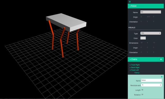
But I want a simple tool to create and manage gaits and animations for legged NodeBot critters.
So I start working on a small browser-based simulation system, mostly as an excuse to explore some web technologies currently missing in my toolbox.
The system will consist of an editor to define the geometry of the NodeBot, and a timeline to control its motion.
The most common method for describing the geometry of a robot, is URDF (http://wiki.ros.org/urdf). URDF stands for Unified Robot Description Format and it is the standard ROS (http://www.ros.org) XML representation of a robot model.
Almost any robot can be described as a kinematic chain of links attach to each other by joints. The least amount of information we need in our system is the length of the links and the type and orientation of the joints. URDF is overkill for this project, so the internal format will be a simple JSON structure.
The editor will be able to save, edit and load geometries. It will also provide tools to customize the visual representation of links and upload STL files to replace the default boxes and cylinders.
The timeline will allow motion control at a higher level than single joint positioning.
It should be able to control the position of a chain’s end-effector using inverse kinematics, to calculate the rotation of the individual joints. The calculation will be perform by Tharp (https://github.com/dtex/tharp), an Inverse Kinematics solver, develop by Donovan Buck (@dtex).